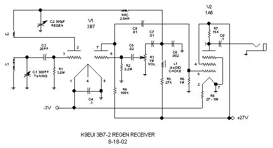
3B7-2 REGEN RECEIVER - K9EUI - 8-18-02
This receiver is the final version of the original 3B7 regen
built breadboard style several months ago.
While many signals were
fairly strong in the original unit, it was felt that an added audio
stage would be a benefit.
The 3B7 was chosen for 3 reasons - I had some on hand, I wanted
a battery operated set, and the 3B7 is
a high frequency tube.
There are many choices for a tube that could be used for the
second audio amp. I looked up the
characteristics of other
tubes on hand and decided on the 1A5 since it is a power pentode
and would probably yield a
fairly good gain and also feed typical
headphones (3K or so) easily. A 1LA4 is the Loktal equivalent.
Overall voltage
gain of the 2 audio stages is 50.
Let me say here that the various resistances were selected to
keep operating parameters, such as biasing,
at proper levels
to insure as distortion-free operation as possible while
getting the most out of the 3 stages while
operating at 27V.
Total B+ current drain is only 2ma!
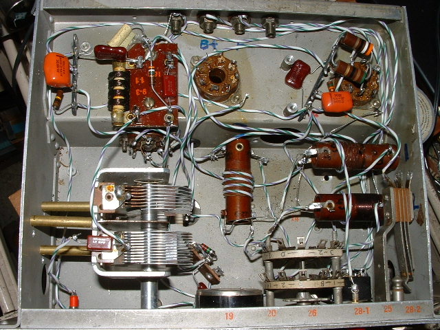
The original set used 1920's commercially made plug-in coils.
This set uses a set of 1/2 inch diameter
coils removed from
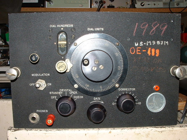
an old mil surplus signal generator. The 3B7-2 is built into
the chassis of a former TS-174 hetrodyne
freq meter (VHF version
of a BC-221). The 3B7-2 has 3 bands covering roughly 2.6 - 5 MHz,
4.1 - 7.6 MHz, and 6.1 - 12
MHz. The original vernier dial of
the TS-174 makes for very smooth, easy tuning. Even covering
as large a range as it
does, SSB can be tuned in very easily.
If one were to use this same dial mechanism with a ham band
only set, the bandspread
would be fantastic.
In the final set, the regen cap is also verniered with an approx
3:1 drive reduction.
Bandswitching is simple, requiring only 2 poles. One pole switches
the plate side of the tickler coil,
while the B+ sides are all
tied together at the RF choke. The 2nd pole switches the hot side
of the tuned winding (L1).
So far, for antenna coupling, I have
one turn of hookup wire wrapped around each coil, all connected
in series, going
to the antenna jack. This seems to work quite well.
Not shown in the drawing is a 20pf cap connected to the plate
pine 2 of the 3B7 brought out to a tip
jack on the front panel.
This is to connect to a scope/counter for calibrating the dial.
In the original set, a 3:1 audio interstage transformer was used
between the detector and audio stage.
Since the TS-174 had the large
audio choke, I used that in the new set. The only real problem I
had with the new set
was an annoying loud audio frequency oscillation
at the point of regeneration threshold. This was cured by adding
the
27K resistor (R5) in the B+ feed to the detector.
For a rough sensitivity reading, a 1/2 microvolt signal at 10 MHz
is easily heard.
Looking at the front panel of the set, The original function switch
is now the bandswitch, the gain control
is audio gain, and the corrector
control is the regen cap. The red bananna jack (where a second phone jack
was originally)
is the antenna post. The orange tip jack is the test
point used for calibration.
Looking at the bottom of the set, the 3B7 socket is behind the regen
variable cap. The center tube socket
is at present unused and may
install an RF amp there. The 2nd audio stage is in the right rear
corner.